Orchestrate fail over of Web Applications in Azure VMs to a DR Site using ASR

Srikantan Sankaran 7/10/2017 6:19:57 AM


With Azure Site Recovery (ASR) it is now possible to orchestrate fail over of workloads like Web Applications running Azure Virtual Machines from a Primary Site to a DR Site. Using Recovery Plans and Runbook Automation, one could script specific configuration actions on the Compute resources that have been recovered by ASR, and bring the Application live on the DR Site. Recovery Services Vault in ASR also provides the ability to simulate and test a Fail over scenario.

Covered here is a scenario where a 2 tier web application, comprising an ASP.NET Forms Application running in an Azure Virtual Machine, connecting to SQL Server 2014 database in another Virtual Machine, are replicated using ASR to another Azure Datacenter.  The steps that are to be performed to complete the replication of the Application to the DR Site, and testing the fail over are broadly as under:

  1. From the Azure Portal, create a Recovery Services Vault in another Azure Data Center, and add the 2 Virtual Machines running in the Primary Data center, as the items to be protected in it.
  2. Enable replication. The Web Server and Database Server VMs would be replicated to the target Data Center

The steps to perform these actions are documented here

As an outcome from the above step, the Virtual Machines images get replicated to the DR Site, and the VNet and Subnet settings mirrored from their counterparts in the Primary Data Center. However, Public IP Address resources that are configured for the Web Server, and the NSG Rules in the Primary Data center are not replicated. These resources need to be added and configured in the DR Site for the Application to be available and accessible. Also, the connection string in the Web.config of the ASP.NET Application needs to be updated with the Internal IP Address of the VM running SQL Server in the DR Site. These configuration steps can be implemented using Recovery Plans, that use Runbook Automation invoked PowerShell scripts.

(Note that no VMs are created in the DR Site yet, but only their images replicated to the DR Site. These images can be spun off into VMs when the fail over happens)

Azure Documentation related to Recovery Plans is available here

3. Create an Automation Services Account in the Target Data Center (Azure DR Site) and add to it the 2 Runbook scripts provided with this article.  Download the scripts from the github location here.

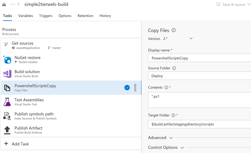
  • Copy & paste the powershell scripts into the 2 Runbooks – the ones referred in this article are SetSqlVmIp.ps1 and asraddpublicip.ps1 – with the same name as the .ps1 files themselves
  • Upload the third PowerShell Script file, UpdateWebConfigRemote.ps1, to Azure Blob Storage, and obtain its public endpoint URL. This would be required later.
  • In the Azure portal, for this Automation Account, create a variable that would store the Private IP Address of the Azure VM running the SQL Server database. In the scenario described here, the Variable name used is PrivateIpSqlDb

There are some changes to be made in the script after the above steps are performed.

  • In the Runbook asraddpublicip, change the values of the following variables, based on the Automation Account and the Automation Account variable name created above.

$AutomationVariableName = ‘PrivateIpSqlDb’

$AutomationAccountName = ‘asrdraccount’


Also, replace the FileUri parameter for the UpdateWebConfigRemote.ps1 uploaded to Blob Storage, in the PowerShell command below.

Set-AzureRmVMCustomScriptExtension -ResourceGroupName $VM.ResourceGroupName `

-VMName $VM.RoleName `

-Name “myCustomScript” `

-FileUri “https://asrdrscriptstore.blob.core.windows.net/scripts/UpdateWebConfigRemote.ps1” `

-Run “UpdateWebConfigRemote.ps1” -Argument $scriptarguments -Location $VMData.Location

  • In the Runbook SetSqlVmIp, change the values of the following variables, based on the Automation Account and Automation Account Variable name used in it, similar to the asraddpublicip Runbook above

$AutomationVariableName = ‘PrivateIpSqlDb’

$AutomationAccountName = ‘asrdraccount’

  • In the PowerShell Script UpdateWebConfigRemote.ps1, there are certain values that are hardcoded in it. While these can be parameterized to make them more generic, for simplicity here, they are retained as they are.

– The Web Application name used is simple2tierweb_deploy,  and it is added as an Application within the ‘Default Web Site’ on IIS on the Web Server. See the screen shot below

– The script looks for a Connection String section with the name miniappdbConnectionString1 within which it replaces the IP Address of the SQL Server VM from the Primary Data Center with that in the DR Site, during failover.


Note: To execute the above Runbooks, the Automation Service requires certain Modules to be available. Import them into the Automation Account in case they are not. Refer to this link for more details on these Modules – the names are:

AzureRM.profile

AzureRM.Resources

AzureRM.Automation

AzureRM.Network

AzureRM.Compute

4. In the Azure Portal, Select the Recovery Services Vault that contains the VMs that were protected in the steps performed earlier, and Add a Recovery Plan. Refer to this link for details on how to create Recovery Plans and this link for details on how to add Runbooks to Recovery Plans.

In the context of the scenario covered in this article, the Recovery Plan would resemble the below after configuration


— Two separate Fail over Groups are created, Group 1 comprising the SQL Server VM, and Group 2 comprising the Web Server VM, in that sequence

— Add a post step to Group 1 and add the Runbook SetSqlVmIp to it. As an outcome of this action, the Internal IP of the SQL Server VM that fails over is retrieved and stored in the Automation Variable PrivateIpSqlDb

Add a post step to Group 2 and add the Runbook asraddpublicip to it. As an outcome of this step, two key actions are performed :

> a PublicIP resource is created and linked to the Network interface card of the Web Server VM.

> The custom script extension is used to execute PowerShell script UpdateWebConfigRemote.ps1 that is stored in Azure Storage. This extension is used to execute this script remotely on the Web Server VM, which retrieves the value of the PrivateIpSqlDb from the Automation variable, replaces the IP Address in the web.config file of the ASP.NET Web Application with this value.

5. From the Azure Portal, choose the Recovery Services Vault, select the Recovery Plan and trigger a Test fail over. Once the fail over completes, from the Resource Group into which the fail over happens, notice that the Web Server and Database Server VMs are created, the Web Server is added to an Availability Set, a PublicIP Resource is added which is assigned to the Web Server VM. See screen shot below


Launch the URL of the Web Application, using the Public IP Address from the the failed over site , as shown above, and you should see the ASP.NET Application working in the DR Site. Shown below is the Web Application and it shows the data obtained from the SQL Server database running in the other VM.


References – I have used the guidance available in the following links and repurposed the scripts in them to implement the scenario in thia article

Runbook Automation – Recovery Plan scripts in technet – here

GitHub Quick Start Template – here

Implementing Service auto scaling in Azure Service Fabric

Srikantan Sankaran 6/25/2018 7:33:46 AM


Azure Service Fabric provides orchestration services for Applications deployed as Docker containers, along with Service level auto scaling. In this example, a Web API is built using ASP.NET Core 2.0, packaged using Docker containers for Linux and deployed to an Azure Service Cluster. A Load Test is run on the REST API to generate CPU load on the Container hosting it, thereby triggering a Service level auto scale rule. This causes additional container instances to be spun up on the other Nodes in the Custer to handle the load, and once the load dies down, these container instances are removed.

To deploy this sample in your own subscription, use the ARM template and the Service Fabric Application Packages in the GitHub Repository – here

Creating the Service Fabric Cluster

This feature requires version 6.2.194.1 + of Azure Service Fabric, and enabling the ‘Resource Monitor Service’ on the Cluster. Since the Azure Portal does not provide an option enable this Service at this time, an ARM Template is used that deploys a cluster with this feature enabled.

The VM Size of D1_v2 is used in this ARM Template to easily simulate the CPU load leading to an auto scale rule trigger

The ARM Template provisions an OMS Repository for Log analytics and monitoring, and to keep the Template simple, the Region used for it is the same as that of the Service Fabric Cluster itself. Ensure that OMS Service is available in the Azure region selected for the Service Fabric Cluster.

Run the ARM Template to create the Cluster. After the Service Fabric Cluster is provisioned, launch the Explorer to check the Cluster Manifest. The Resource Monitor Service would be enabled. See below


The REST API used in the sample is packaged as a Docker Container and uploaded to Docker Hub, and is referenced in the Service Manifest of the Service Fabric Application available with this article.

Deploying the sample Application to the Service Fabric Cluster

Navigate to the folder where this GitHub Repository is cloned to. The ‘app-packages’ folder contains the Application packages in the sample. Use Git Bash or other tools to deploy the Service Fabric Application.

Key configurations implemented in the package for auto scaling

– For auto scaling to work, the ServicePackageActivationMode needs to be set to ‘ExclusiveProcess’ (the default mode is ‘shared’)

– The auto scale trigger rule and metric name and threshold values need to be specified. Refer to this link for details.

– The instance count for the Service type is set to 1. When the auto scale kicks in, more instances of the container would be activated in the Service Fabric Cluster.

The section from Application Manifest file relevant to this configuration is shown below.

<ApplicationManifest>

<DefaultServices>

<Service Name=”sfapi” ServicePackageActivationMode=”ExclusiveProcess”>

<StatelessService ServiceTypeName=”sfapiType” InstanceCount=”1″>

<SingletonPartition />

<ServiceScalingPolicies>

<ScalingPolicy>

<AveragePartitionLoadScalingTrigger MetricName=”servicefabric:/_CpuCores” LowerLoadThreshold=”0.5″ UpperLoadThreshold=”0.70″ ScaleIntervalInSeconds=”120″/>

<InstanceCountScalingMechanism MinInstanceCount=”1″ MaxInstanceCount=”3″ ScaleIncrement=”1″/>

</ScalingPolicy>

</ServiceScalingPolicies>

</StatelessService>

</Service>

</DefaultServices>

</ApplicationManifest>

The relevant config from the Service Manifest for the Application is a shown below, that refers to the Container image uploaded to Docker Hub.

<ContainerHost>

<ImageName>srikantan67/sfwebapi2:Version06</ImageName>

<Commands></Commands>

</ContainerHost>

Connect to the Cluster and install the application

sfctl cluster select –endpoint https://<yourcluster&gt;.<region>.cloudapp.azure.com:19080 –pem opennetclcert.pem –no-verify

./install.sh

Ensure the Application is running: url in this sample – http://auscsfcl0.southeastasia.cloudapp.azure.com:5002/api/Operations

In the Service Fabric Explorer, you will observe that only one container instance of this application would be running in one of the Nodes in the Service Fabric Cluster.

Enable the OMS Agent for Linux in the VM Scale set running Service Fabric

(optional step. Required only to view the metrics in the OMS Repository)

This agent is required in the Nodes running the containerized Application, to capture the container logs and push them to the OMS Repository. These are to be activated after the application is deployed to the Cluster, since Docker has to be installed on the Nodes prior to activating this Extension. Refer to this for more details. For the OMS Solution for Service Fabric, refer to this link.

From the Azure Portal, obtain the Workspace ID and Secret of the OMS Repository and execute the CLI command below:

az vmss extension set –name OmsAgentForLinux –publisher Microsoft.EnterpriseCloud.Monitoring –resource-group <ur sf rg name> –vmss-name <ur sf vmss name> –settings “{‘workspaceId’:'<oms workspace id>’}” –protected-settings “{‘workspaceKey’:'<workspace key>’}”

This actions takes a few minutes to complete.

Run a Load Test and test the service type level auto scaling

I have used Application Insights to configure a manual load test that hits the REST API url with 1500 concurrent users, and a test duration of 15 minutes.


View the Service Fabric Explorer

Observe the Service Fabric Explorer as the test progresses. After some time, you will notice additional container instances running in the other Nodes in the cluster. After the test completes, the additional container instances would get removed from the Explorer view.

View the Container logs and Node metrics of Service Fabric as captured in OMS

Launch the OMS Workspace and launch the Container Logs and Service Fabric Solutions (these were deployed in the OMS Workspace when the ARM Template was run).

The screen shot below shows how over the course of the Load Test, additional container instances were deployed in the other Nodes in the Cluster, on trigger of the auto scaling rules. Once the Load came down on completion of the Test, the additional container instances were removed by the auto scaling rule.


Below is a screen shot from the Container log Solution in OMS, for the duration when the Load test was run.


Deploying containerised Asp.net Core Applications to Azure

Srikantan Sankaran
4/3/2018 1:23:39 AM


In the March 2018 issue of MSDN Magazine (msdn.com/magazine/mt845653), was covered a scenario in which insurance policies for vehicles generated by an agency could be stored securely in Azure Key Vault as secrets, and how additional features like asymmetric encryption with keys and built-in versioning could be used to maintain an audit trail of access to insurance policies. The applications that used Azure Key Vault were deployed to Azure App Service as Web apps. In msdn.com/magazine/mt846465 article, the same applications would be containerized and deployed to Azure Container Services for Kubernetes (AKS). 

Deploy Web Application to Azure VM Scale Sets using Packer and Team Services

Srikantan Sankaran 6/26/2017 5:27:04 PM


Summary

Build and Release automation in Team Services helps to deploy ASP.NET Web Applications to Azure Virtual Machine Scale Sets (VMSS) through immutable Virtual Machine images that are created using Packer. Azure Visual Studio Team Services provides ready to use Templates for adding Build and Release Tasks that implement this integration with Packer. Through this automation, the a VMSS running in Azure is updated with a new VM image that contains the updated code in the Application.

Artefacts used in this article

The artefacts can be downloaded from the GitHub Repository here. Added to the Visual Studio 2015 ASP.NET Solution is a folder ‘Deploy’ that contains 2 PowerShell scripts that are described here


1. DeployAspApp1.ps1  -> Is invoked from the ‘Build immutable image’ Packer Task in Azure Team Services. It is used to

  • prepare a new Windows Server VM from the Gallery, enable the role of a Web Server, download and install msdeploy.exe and tools
  • Use the Web Application Package of the ASP.NET Application from the Build Step in the CI Pipeline, deploy that into IIS on this VM using msdeploy.exe

2. vmsscreateorupdate.ps1  -> is invoked after the creation of the custom image by Packer. It is used to

  • Create a new VMSS instance in Azure if it does not exist already, using the custom image created in the previous step
  • OR, update an existing VMSS instance with the custom image created in the previous step

Using the artefacts in the Solution

  • Add this Visual Studio 2015 Solution to a Team Services Repository in Azure
  • Create a Build Definition for the Solution in the Code respository. Configure the trigger to invoke this pipeline
  • Create a Release Definition that would be triggered when the Build Process above executes

These steps are covered in more detail below

Build Definition in Azure Team Services

  • Create a new Build Definition and use the Template – ASP.NET (Preview)
  • Configure all the tasks in the template, link it to the Project Source code repository created for the ASP.NET Application
  • Add a task ‘Copy Files’ to this Pipeline and configure it to copy all the PowerShell scripts to the Build Output location, inside the ‘scripts’ subfolder. This step is required since the ‘Build Solution’ step creates a Web Application Package for the ASP.NET Solution alone. We need to copy the PowerShell scripts manually using this step. See screenshot below with the highlight, for the configuration.


Release Definition in Team Services

  • Define variables to capture the configuration of the VMSS to create or update. See screen shot below


  • Create a new Release Definition and choose the ’empty’ Template
  • Add the Task ‘Build Machine Image (PREVIEW)‘ from the Gallery and configure it as shown in the screenshot below.
    • For the Field ‘Deployment Package’ > Select the location of the ‘drop’ folder from the Build Step in CI, where the Web Application Package was dropped to
    • For the field ‘Deployment script’ > Select the DeployAspApp1.ps1 after prefixing it with the subfolder name
    • The custom image is created as an outcome of this step and its URL is stored in the variable  ‘p_imageurl’ configured in this Packer Task. See the screenshot below


  • Add an ‘Azure PowerShell’ Task from the Gallery, and configure it to point to the vmsscreateorupdate.ps1 script. This script takes 3 parameters that need to be mapped to the variables defined in the previous steps. Map the URL to the output Image from the Packer Task. This script creates or updates the Azure VMSS. See screen shot below


  • In the ‘Trigger’ tab of the release Definition, select the option to trigger the CD Process after the CI Process executes.

Test the Scenario

  •  Trigger the CI Step by either checking in the Source code from Visual Studio, or manually ‘Queue’ a Build from Team Services
  • Ensure the Build (CI) Process completes successfully. This should trigger the CD process. Select the Release process that was triggered and navigate to the ‘Logs’ tab. The console output from the execution can be viewed
  • The screenshot below shows the console output from the execution of the PowerShell commands in the Packer Task. Ensure that the deployment of the Web Application Package is successful. screenshot below with the Console output from the run


  • Launch the Azure Portal, and view the contents of the Resource Group ‘autoweb’. Launch the URL <PublicIP of the VMSS>/simple2tierweb_deploy. The Web Application should be visible.
  • Update the application code and check in the Source code. Trigger the CI and CD Processes in Team Services. On completion of the CD Process, the update Web Application should be available on the above URL

Calling Azure Cosmos DB Graph API from Azure Functions

Srikantan Sankaran 7/21/2017 7:07:25 AM


Azure Functions at this time provides Input and output Bindings for DocumentDB, one of the Database Models in Azure Cosmos DB. There aren’t any for Cosmos DB Graph yet. However, using the ability to reference external assemblies and importing them through NuGet Packages, it is possible to access these APIs from the C# Scripts in Azure Functions.

1) Create a Graph Container in CosmosDB

I have used the starter Solution available in the Documentation for Azure Cosmos DB, that showcases how to use .NET Code to create a Cosmos DB Database, a Graph Container in it, and inject data using the Graph API into this container. It also shows how to query the Graph using the APIs. Once this Starter Solution is deployed, you could use the built in Graph Explorer to traverse the Graph and view the Nodes and Vertices.


2) Create an Azure Function App

Create an Azure Function App, add a Function in it; use the HTTPTrigger Template in it if this Function ought to be invoked from a Client Application. For this exercise, I have used a TimerTrigger Template in C#.

3) Reference external assemblies in project.json and upload this file to the Function App Deployment folder

The project.json that I used and the assemblies that had to be referenced were:

{

“frameworks”: {

“net46”: {

“dependencies”: {

“Microsoft.Azure.DocumentDB”: “1.14.0”,

“Microsoft.Azure.Graphs”: “0.2.2-preview”,

“Newtonsoft.Json”: “6.0.8”,

“System.Collections”: “4.0.0”,

“System.Collections.Immutable”: “1.1.37”,

“System.Globalization”: “4.0.0”,

“System.Linq”: “4.0.0”,

“System.Threading” :  “4.0.0”

}

}

}

}

The project.json file needs to be uploaded to the location https://<function_app_name>.scm.azurewebsites.net. The Azure Documentation here  and here outlines the steps required to be performed.  See screenshot below:


4) Add environmental variables to the App Settings of the Function App

This is to store the Graph Connection information in the environment variables of the Function App


5) Adding the C# Scripts in the Azure Function that calls the Graph API


I have repurposed the code from the Starter sample referred earlier in this article, made minimal changes to suit this article. The Gremlin query used here sorts all the Persons (Nodes) in the Graph, sorted descending on their First Names

Trigger this function and view the results from the execution of the Gremlin Query, in the execution log


Aggregation of OMS Data from across Azure Subscriptions

Srikantan Sankaran 6/27/2017 5:17:53 PM


An Operations Management Suite (OMS) Repository can be associated to a single Azure Subscription. Companies that host their Products on separate per-tenant Azure Subscription for their Customers have this need to consolidate the Health data from all these Subscriptions for ease of monitoring and tracking. OMS provides the ability to configure Alerts that would call a Web Hook configured on a Central Incident Management System. The IT Support Team could then track and diagnose issues in their  Solution deployment. However, when there are no such Systems implemented, an alternative approach would be to host a Common OMS Workspace to which the individual, per tenant Workspaces would send the Health data to, using the Data Collector APIs.


Aggregation of Heartbeat data from Compute Resources in Azure

The PowerShell script VMsHeartbeatAggregator.ps1 that implements the aggregation logic is called from an Azure Runbook. The Runbook executes under an Azure Automation Account and has a scheduler configured to recurrently trigger the PowerShell script.

The PowerShell script executes a Dynamic Query on OMS to retrieve aggregated Heartbeat Data from the VMs and VMSS deployed in that Subscription. This data is then pushed to the Common OMS Workspace using the Data Collector API. This Runbook would be deployed in each of the Azure Subscriptions and the data captured from these OMS Workspaces is aggregated to a single, common OMS Workspace.

The Data Collector API (REST API) does not insert or update data into the Record Types that OMS provides by default, namely Heartbeat, Event, etc. It is required to create a custom Record Type into which the data is pushed using the API. Assign different Record Type names in the Common OMS Workspace corresponding to each Source OMS Workspaces that sends the data.

View Designer and Custom Views can be used to create the Dashboard in the common OMS Workspace, one for each Source OMS Workspace. Provide hyperlinks in these Dashboards back to the Dashboards in the respective Source OMS Workspace. This lets the Help Desk Team drill down into the raw data in the Source Subscriptions to investigate an issue.

The PowerShell scripts used to implement this scenario can be downloaded from the GitHub Repository here It is based on the elaborate guidance on the invocation of the Data Collector API using PowerShell, which is covered in the Documentation here

The key steps to be performed to implement this scenario are:

  • Configure a Log Analytics Resource and add the VMs and VMSS Resources to be monitored to it. An OMS Workspace corresponding to the Log Analytics Resource is created where the Heartbeat information is sent to. Refer to the Azure documentation here to get started
  • Create an Azure Automation Account from the Azure Portal
  • Within the Automation Account, navigate to Runbooks> Add a new Runbook
  • Edit the runbook and paste the PowerShell script from VMsHeartbeatAggregator.ps1 into it

To execute this script, certain PowerShell Modules need to be imported first, as shown in the screenshot below. At the prompt, acknowledge the installation of the Dependent Modules as well.


  • Add a Scheduler to the Runbook created above. Since the PowerShell script uses input parameters, the Scheduler configuration form would prompt for these values. In the scenario implemented here, the input parameters used are:

[Parameter (Mandatory=$true)]

[String] $ResourceGroupName,    -> Resource Group that contains the VMs and VMSS being monitored

[Parameter (Mandatory=$true)]

[String] $WorkspaceName,   -> Source OMS Workspace Name where the Heartbeat data is queried upon

[Parameter (Mandatory=$true)]

[String] $CustomerName,     # e.g. CustomerX for whom the solution is deployed

[Parameter (Mandatory=$true)]

[String] $EnviromentName     # e.g. staging

The values of $CustomerName and $EnvironmentName are concatenated to form the name of the Record Type created in the Common OMS Workspace.

In the PowerShell script, set the values of the following variable pertaining to the Target Common OMS Workspace

# This is the Unique identifier of the Common Workspace in OMS

$CustomerId = “[Enter the Common OMS Workspace ID]”

# The access key to connect to the common OMS Workspace

$SharedKey = “[Enter the Access key required to invoke the Data Collector API on the common OMS Workspace]”

These values can be obtained from the OMS Workspace Data Source Settings Page, as shown in the screenshot below


  • Execute the Runbook manually, or use the Scheduler to trigger it. View the Console output and ensure that there are no errors.
  • Navigate to the Common OMS Workspace and use Log Search to view the data inserted using the Data Collector API. Note that the Record Type name is suffixed with _CL by the API. See Screenshot below.


  • Likewise execute the Runbook in each of the Source Subscriptions and push the data to the corresponding Record Type in the Common OMS Workspace.
  • Use View Designer or Custom Views in the Common OMS Workspace to create a Dashboard for data inserted for each Record Type

Azure Web App Monitoring with Alerts

The PowerShell script WebAppHealthcheckRunbook.ps1 in this sample is deployed in a Runbook that exposes a Web hook.

  • An Azure Application Insight Resource is configured to execute Web App URL Ping Tests
  • When the outcome is a failure an Alert can be raised which would call the Web hook configured for the Runbook and pass the details like the Web App Name, Resource Name, etc to it
  • The Power Shell script would then invoke the Data Collector API of the common OMS Workspace and insert the Ping Test result data into a custom Record Type

Guidance on working with Webhook in a Runbook is covered in the Azure Documentation Link here 

The screenshot below shows how Application Insights can be configured to execute Ping Health Checks on a Web App, and how an Alert could be configured to invoke the Webhook exposed by a Runbook.


Power BI Embedded – Row Level Security

This sample shows how Row Level Security can be implemented in a Power BI (PBI) Embedded Application. The Power BI Service Subscription is owned by a Company ‘A’, and a PBI Pro User in this Organization builds the Reports and Datasets and publishes them to the Service. Since these reports would be accessed by Users in an external organization (Contoso, in this example), these reports are embedded in an ASP.NET Mvc Application.

About the data used in the Reports

The base data, shown in Figure 1, used in the Reports is from the table ‘Customers’ that contains a ‘Country’ Column. Sales Managers in Contoso are associated to one or more Countries. In this example a user johndoe@contoso.com is associated to 2 countries whereas others are associated to one each. It is required that when Sales Manager access the Reports, they ought to see only those Customers that lie in Country they are associated with.

Figure 1 Azure SQL Database Tables

About the PBI Report and Data Set

A simple Tabular report layout, shown in Figure 2, is chosen to display the data. Relations were defined in the tables to relate the ‘Country’ Column in the ‘Customers’ and ‘SalesManagers’ Tables to the Master Table ‘Countries’ – Figure 3 below.

Figure 2 PBI Desktop Project

The security filter is set to bi-directional, as shown below.

Figure 3 Customer Table Relations

Definition RLS in PBI Desktop

For RLS, we need a combination of Roles, Users and Rules

  1. Users

Users are defined in Azure SQL Database table (shown above).

Note Power BI Service provides the option where User to Role Mapping can be defined on the Report after it is published. Users can be picked up from Azure AD directly and assigned to the Roles. However, in this case, the users accessing the Report are external to the Organization hosting the reports and cannot be picked up from the Azure AD Tenant. These external Users are defined in the Database instead.
  1. Roles & Rules

Roles ‘SalesManager’ and ‘SalesManagerIndia’ are defined in this sample. (See Figure 4 and Figure 5)

Rule for Role ‘SalesManager’ : Defined On Table ‘SalesManagers’, a DAX Expression is defined to return the Country Names associated to the User Name in the Request. In this case, if a SalesManager is linked to one or more countries, all those records will be returned.

Figure 4 RLS Roles and Rules

Rule for Role ‘SalesManagerIndia’ : A UserName filter is applied on Table ‘SalesManagers’ as above, and additionally, an filter on ‘customers’ table is applied to filter only the records where the ‘Country’ is ‘India’. (See Figure 5)

Figure 5 Roles & Rules

Testing the RLS in PBI Desktop

Selecting ‘SalesManager’ as Role and User ‘johndoe@contoso.com’ returns Customer records from both countries where this User is a SalesManager.

Figure 6 RLS -1

Selecting Role ‘SalesManagerIndia’ for the same User now returns only ‘Customers’ records in ‘India’. This shows that for the same User based on the Role Name, different RLS criteria can be applied.

Figure 7 RLS – 2

Publish the Report

Publish the Report to Power BI Service. Next, embed the Report in an application. For this example, to embed this Report in an Application, the documentation steps and the sample ASP.NET Mvc Application provided in this link were used.

Running the PBI Embedded Application

Download the Visual Studio 2017 Solution for the sample Application referred above, make changes to the Web.config file to change the Report ID, Workspace ID in it to point to the ones used to deploy the Report in the earlier steps.

Launch the Solution locally from Visual Studio 2017, enter the User Name and Role name to check RLS.

Figure 8 RLS on PBI Embedded Application

No code, Business process automation to generate Documents based on Templates

Abstract

Organizations have this need to implement a Business process to automate the approval and generation of Documents. While a generic process to implement this is extremely simple, with Office 365 SharePoint and Microsoft Flow, it is not uncommon to have requirements where the documents ought to be based on certain Templates, which is chosen by the requestor of the document. Also, while the approval workflow process would be bound to the Document Library, organizations would want to segregate the request capture process itself from the document generation and download. They may, for e.g. want the requestor to have read-only access to the document generated, while they could have read-write permissions in the Approval Request capture process.

Microsoft Flow, Powerapps and Office 365 SharePoint could be used to meet these requirements using an approach that entails zero code. Organizations could use these technologies to implement such automation without having to depend on internal IT to code such solutions, and at a fraction of the time that it would otherwise take.

Solution approach

Office 365 SharePoint Team Site is created that would contain several artefacts that are referred to in the sections below.

A custom List PolicydocsIssuanceRequests is where the Requests are captured. The Document requestor enters information like the Customer Name, the Document Type to be generated (whether it is a ‘Statement of Work’ format or whether it is a ‘Warranty Details’ format that needs to be created for the Customer), select a signatory (person who would approve this document generation request & the signatory). Selecting the Customer Name sets additional attributes like the Customer Address and their contact information automatically, using Look up fields that refer to a CustomersList Custom list. Requestors would have read-write access to the PolicydocsIssuanceRequests List, since they ought to be able to submit information.

PolicyDocsRepo is the Document Library where the Documents that are generated on approval get stored. Requestors would have read-only access to this Library. The same columns that exist in the PolicydocsIssuanceRequests List are created here too(see the screenshot below). A Microsoft Flow process bound to the PolicydocsIssuanceRequests List copies these attributes to the PolicyDocsRepo Document Library.

The PolicyDocsRepo Document Library should be configured to support Documents based on multiple Word 2016 Document templates. Authors of the Template ought to be able to access the field values in the Document Library and insert them as placeholders inside the document templates.

Use the guidance in this article to define the different Word 2016 document templates. From the Library Settings>Advanced Setting>, open templates.dotx. Edit the default template and make changes to it to suit each of the formats in this article (Statement of Work and Warranty templates), and save these as StatementOfWork.dotx & Warranty.dotx respectively to the PolicyDocsRepo Document Library.

The attributes from the Document Library are visible inside Word 2016 – (screen shot below). Place these fields in the relevant sections of the Document template.

To use these templates in a Microsoft Flow process, a Word 2016 document is created from each of the templates above and saved in the .docx format. To do that, simply open the .dotx templates from the Document Library and do a ‘save as’ to your local computer. Then upload these documents (e.g. in this article, the document names are as shown in the screenshot below) to the BlankPolicyDocuments Library.

Next, a Microsoft Flow process is configured on the PolicydocsIssuanceRequests List. Select the ‘Start Approval when a new item is added’ Template.

Post approval of the Request, based on the Template Type selected in the Request, the Switch/case branches out into a separate path.

The ‘Get File Content’ action under the path for ‘Warranty’, gets the WarrantyBlankFormat.docx from the BlankPolicyDocuments Library, and in the action Create File’, inserts that into the PolicyDocsRepo Library. At this point it does not contain the column values from the Request submitted earlier.

The ‘Update File properties’ action, gets the link to the Document inserted in the ‘Create File’ action, and updates the column values in the Library with those captured with the initial Request. (screen shot below)

The ‘RequestTrail‘ column value is set to the URL of the Request in the PolicydocsIssuanceRequests List, for trace back and reference.

To test the process, create a new Item in the PolicydocsIssuanceRequests List, and use the default Edit Form the Custom list provides. However, to make the process simpler for the end users, from the list menu options, choose to create a Powerapps App for this List. The UI generation Engine builds the App automatically. Only minimal changes are required to be done. It uses certain attributes in the UI which you might not need. Just select those fields and replace them with the required fields from the Library. (See screens hot below)

Run the App and submit the request. Choose a Document template type (PolicyDocumentType in the screenshot below) to be used for the Document generation. An approval email is sent to the user selected in the ‘Signatories’ field in the App. Once approved, a document is generated and uploaded to the PolicyDocsRepo Document Library, using the Template chosen in the request.

Once the Powerapps App is tested, it would be published to Powerapps Service and then shared with other users in the Organization. Users would install Powerapps on their Android or iOS devices, and when they login with their Corporate credentials in Azure or Office 365 Active Directory, the published App would be visible to them.

Now users could submit this Document generation request even while on the move, using the Powerapps App on their Mobile phones or Tablet devices.